CPU Power Supply Mod
This project came out of wanting to etch my first useful PCB, as up to now all the PCBs I’ve made have been tests. I have a old CPU power supply thats been lying around for awhile, so I decided to convert it to a PSU I could use on my bench.
First I started googling around for info on it, and found that it uses a standard computer PSU pin-out called ATX 2.x. The wikipedia article on it is here.
The specifications for the power supply are as follows:
- +3.3VDC/17A
- +5VDC/22A
- +5VDC/2A (Standby)
- +12VDC/18A
- -12VDC/0.8A
- 300W Max power
I’m planing to make all the circuitry handle about 3A maximum current draw on each channel. I’m going to fuse it for 2.5A for now though. If I ever want to be able to draw more current then that, which is not likely, I guess will just have to modify it some more. :D
So to the first order of business - draw a schematic. Here it is:
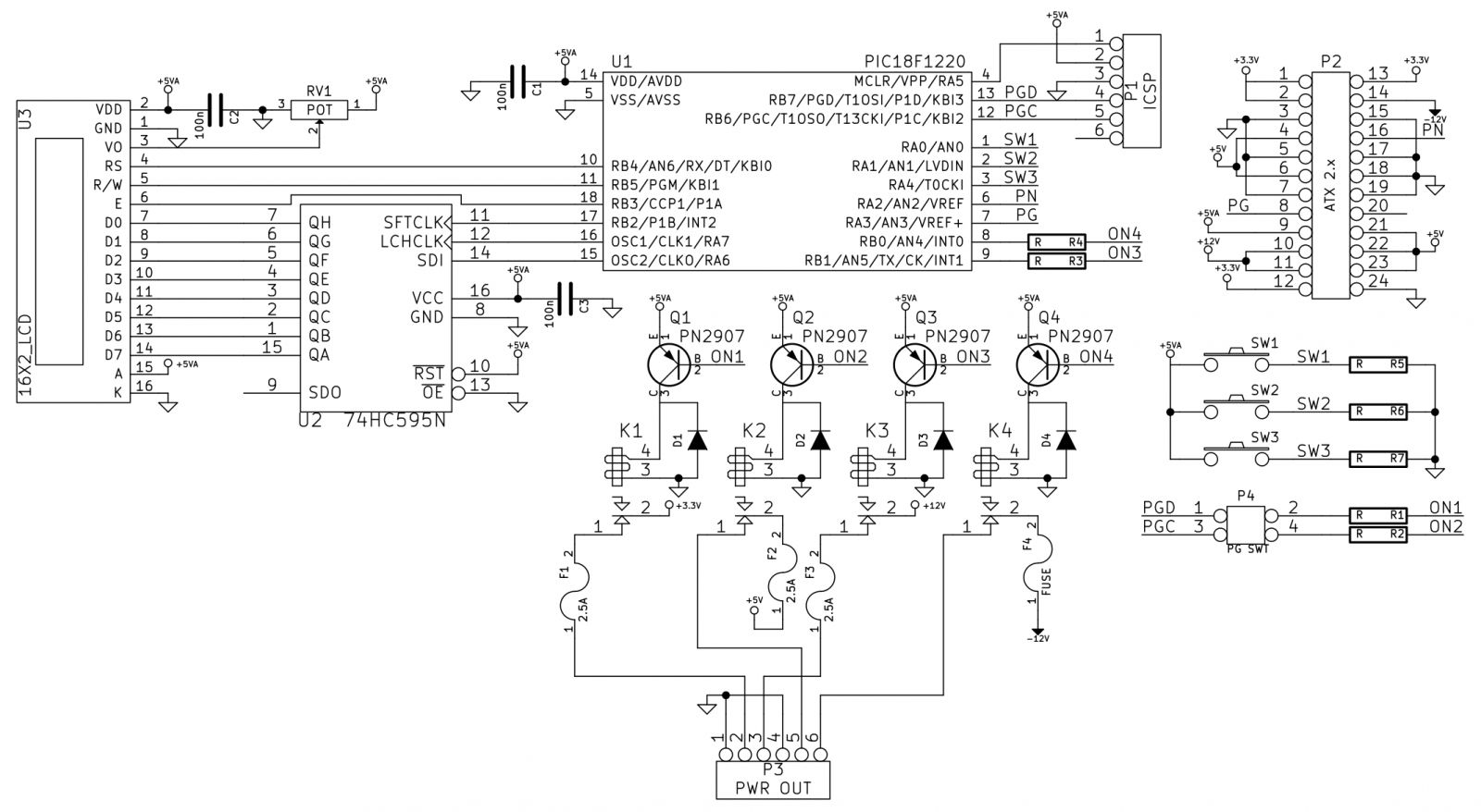
I decided to use a PIC18F1220 for this project because I have quite a few laying around. A 1602 LCD will be used for the user interface – I’ll need some way of telling the user which voltages are switched on. Three switches will work for user control (Select/up/down – or something like that).
P4 is a jumper, it connects PGD to ON1 and PGC to ON2, and is there for when the PIC is programmed. Since I ran out of I/Os I had to use the two pins that are for programming the PIC. And when the PIC is programmed I don’t want anything screwing up the communication between the computer and the PIC, so P4 should be unjumped while programming (is that even a word? :D).
Here’s the PCB layout:
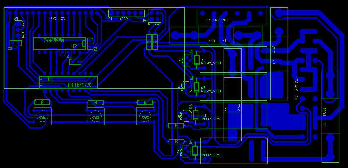
Yes, I know that the fuses overlap other parts - The plan is to have the fuses mounted on the back side of the circuit board and the rest of the parts on top. The relays are some high current ones that I salvaged from a used circuit board, I think they where out of a broken fryer to be exact.
Unfortunately, I will have to solder about eight jumper wires on where I couldn’t figure out how to run a trace, not shown here but they can be seen in the KiCAD file as un-routed traces. I guess I should have tried to optimize it a little more, but space was kind of lacking…
On to etching!
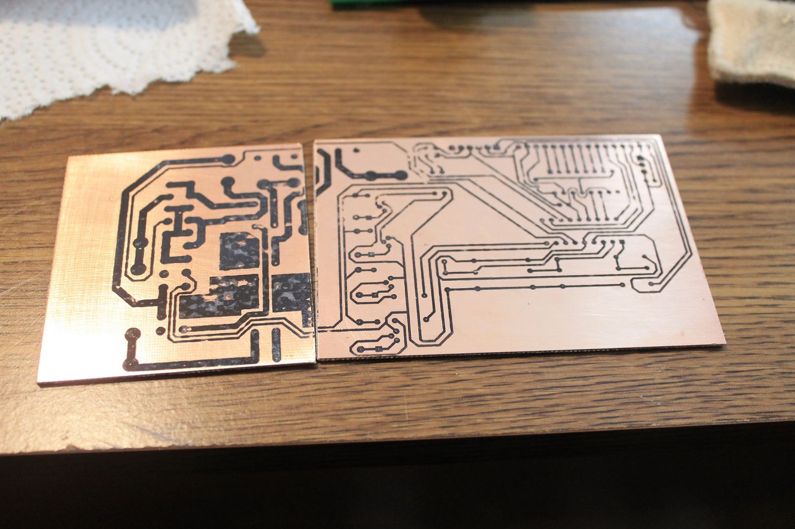
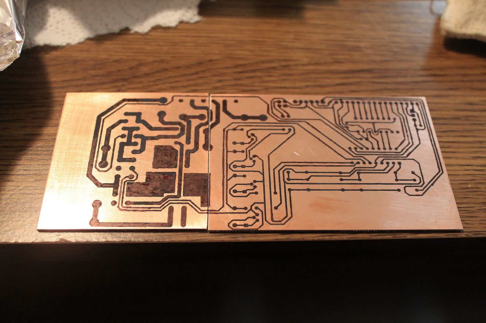
The first photo is right after the toner transfer. As you can see, there are quite a few spots where the toner did not stick ideally. The second photo is after touching up with a sharpie.
I think I may have rushed the toner transferring part a little, and that’s why it didn’t turn out so good. I could have redone it, but I didn’t want to use up any more of my all to little supply of glossy paper.
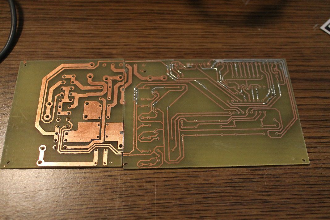
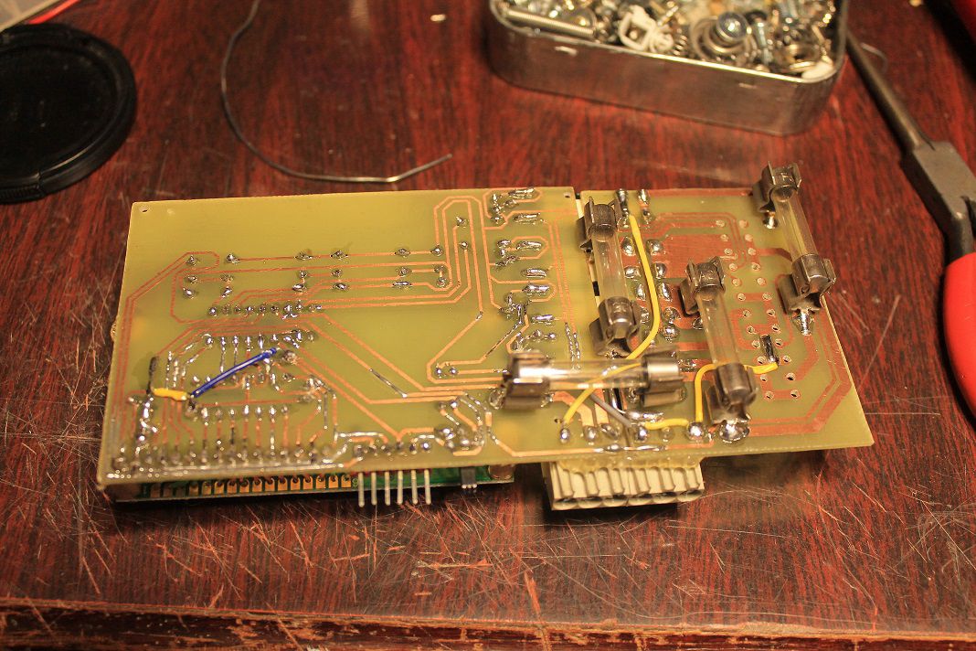
So after etching, I realized that sharpie is probably not the best resist. It appeared that some had come off during the process… Here’s a photo of the PCB after patching the broken traces with solder (sorry I forgot to take a photo right after etching):

The next step will be drilling the holes on the PCB. But unfortunately my drill bits haven’t arrived yet, so I will just have to call it for now.
Update on 10/7/15
The drill bit’s came in!
I also decided to try and put a silkscreen on the board.
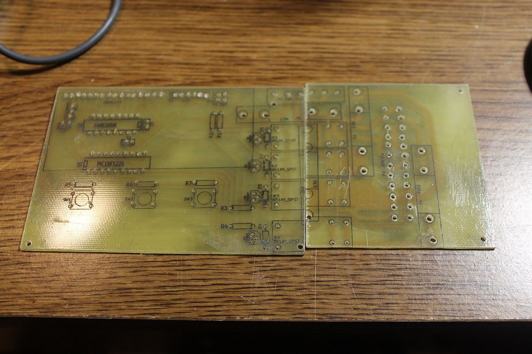
I used the same method as I did for the copper side. But as you can see, on the right side of the left board the transfer moved and blurred out. It doesn’t really matter much though, as this was more of a test to see if I could do it, and also the relays will cover it up.
Next step - Soldering!
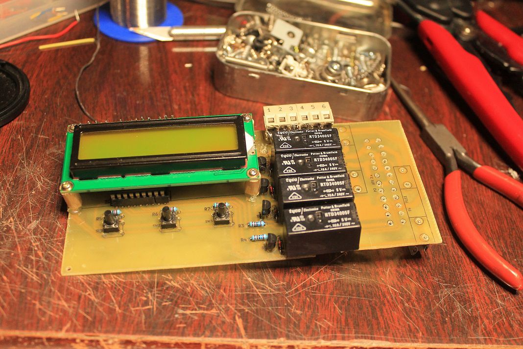
Everything soldered up pretty nicely. I used stranded wires for the LCD connections so it could be pulled backwards if I need to get at the parts under it. I decided to mount a switch instead of a jumper on P4, which should make it a little less painful to program it.
Everything was going good until I realized that somewhere along the line the connector for the power supply got mirrored on the PCB! I guess I will just have to hand wire it. *cries*
Update on 10/13/15
So I opened up the power supply case to cut out some wires that I don’t need for this project, and looky what I found:
I think this power supply has had a lot of hours running. As I remember though, the computer I pulled it from still worked, so I think I will just over look that for now.
Next I made a chassis out of the metal from an old popcorn can (it’s tin so it solders nicely), and attached the circuit board to the power supply.
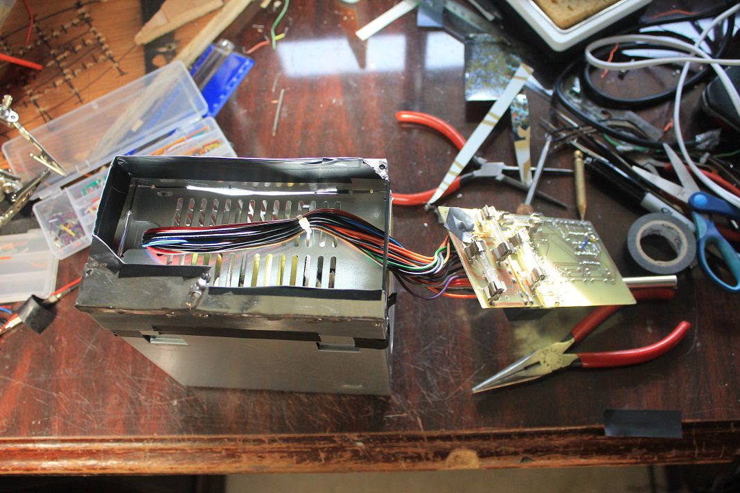
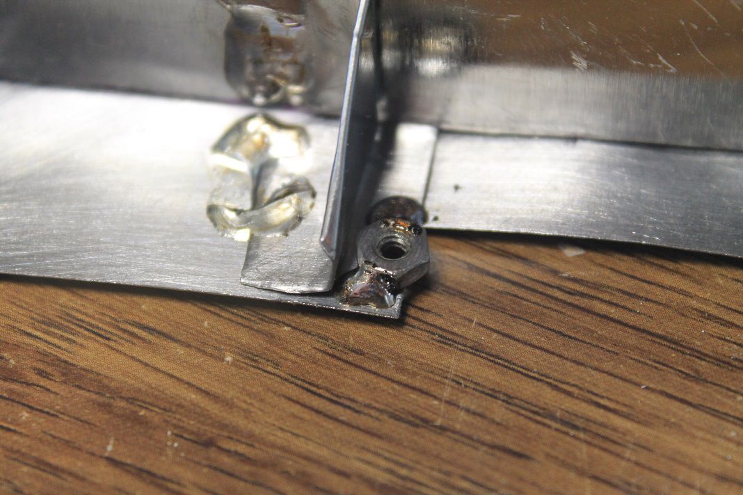
Photo two is a nut I soldered to the chassis so I could attach the circuit board to it with screws (aka make it easy to take apart and troubleshoot when it doesn’t work - lol!). I had to get out the weller 140W soldering gun to make the joints, as my regular soldering iron just couldn’t cut the mustard.
It lives!!

The display looks kind of weak, but it may just be a bad LCD.
Next step will be to write some code.
Update on 10/29/15
I guess the next step isn’t going to be writing code - instead it will be troubleshooting the PSU!
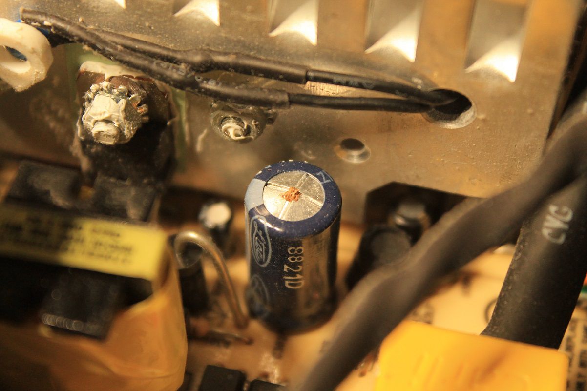
So after playing around with a little code, things just didn’t seam to be working right. I decided to check the standby voltage, and to my great surprise it read about 2.8VDC, not 5V as expected! So I hooked it up to the scope (being careful to hook ground up in the right spot) and here’s what I got:
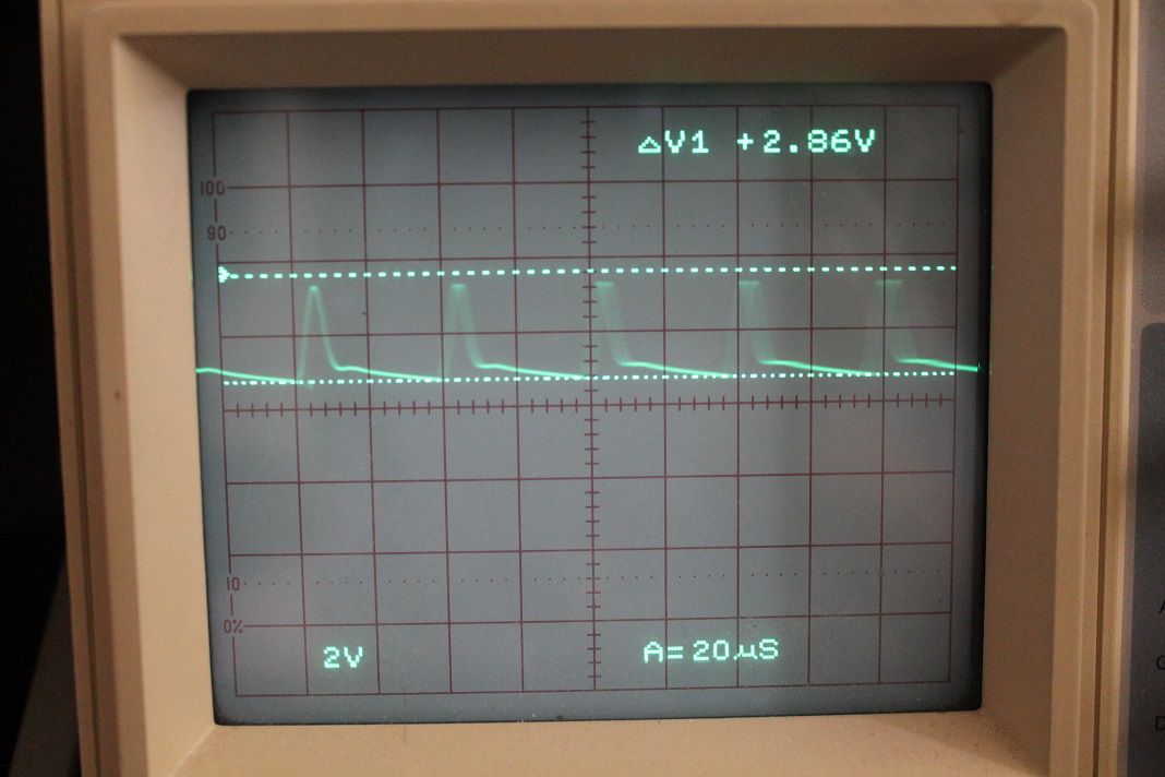
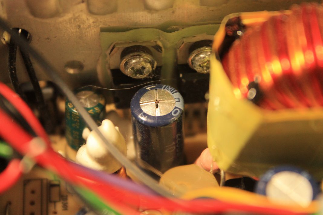
looks like the fault of a seriously bad capacitor to me! So I wrote down the values of all the caps that looked suspicious and bought some new ones from digikey (of much higher quality).
After putting the new caps in, I turned it on and the problem seamed to still be there… After some more experimenting I found out that all the screws that hold the PSU circuit board in place have to be in for the unit to work - they connect to the metal chassis completing the ground plane. It now works great! All the voltages are nice and flat, and the LCD works a lot better too.
Update on 11/14/2015
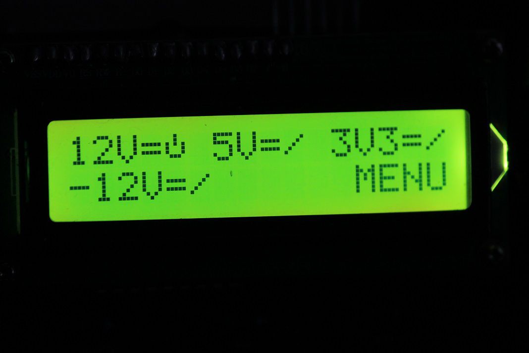
Well, I finished the code and posted it on github. Here’s a photo of the power supply’s main screen while running:
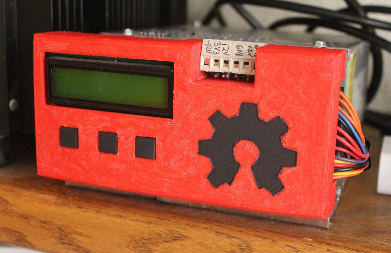
And the finished power supply above my desk:
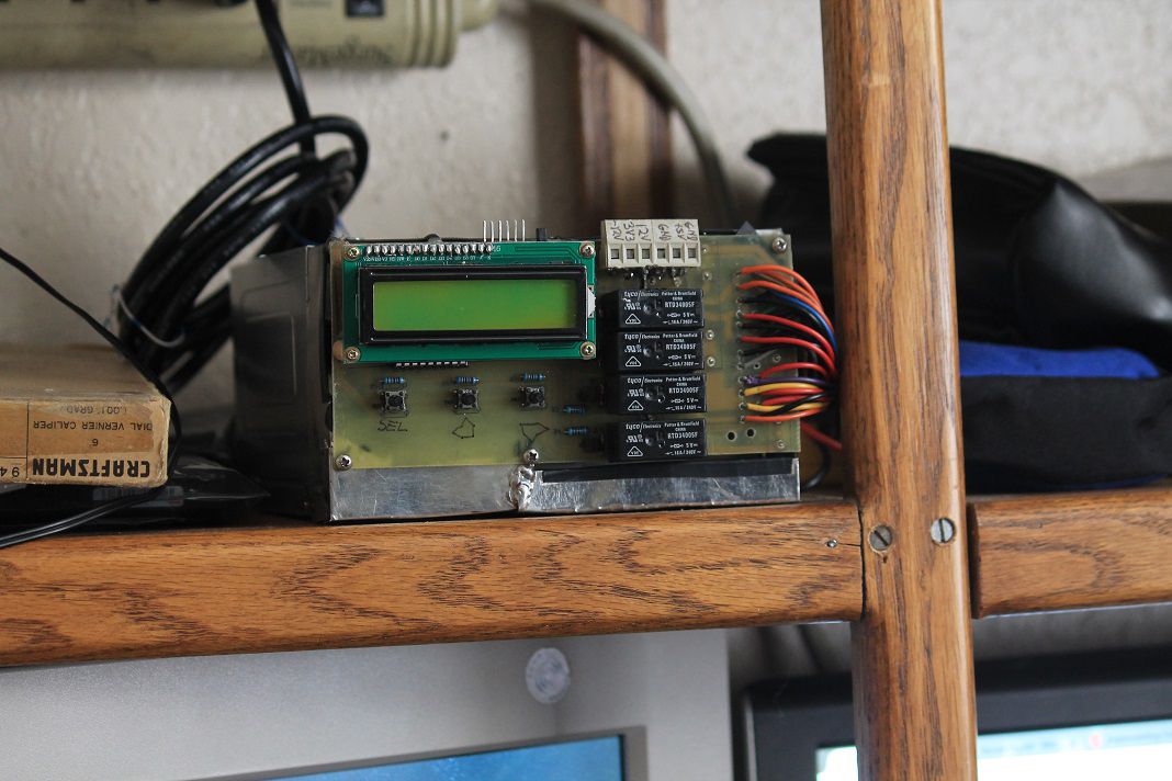
I’m pretty happy about how it turned out. It doesn’t look very good from the front though. I’ll probably end up making a cover for it some time in the future.
Update on 6/15/2016
So I finally got around to making a front cover for the PSU. I recently acquired a 3D printer, so I thought I would finish up the project with a nice cover for the front. And with a little paint, it looks really nice:
