So with summer approaching, I needed a project to keep me busy. I knew I wanted to build something small and reasonably cheap, that I could finish before summer ends. I decided to make a Smart Watch with a target price around $100.
I started looking around for other smart watch builds for examples, since I was having a hard time finding the right parts for mine (finding the right size of display was the main problem). I came upon this build: http://jared.geek.nz/2014/jul/oled-watch-is-alive. It was built very well, so I kind of used it as a guidebook as I went along with this project. This project is in no way a direct port of that project, but it does have a few similarities, as I used the same battery charger as he did and a similar screen - But that’s about it.
Next step: Design. The schematic for the project can be found here: https://github.com/Supercap2F/Smart-Watch/blob/master/KiCAD/SmartWatch.pdf. The processor for the watch is a 32-bit PIC microcontroller (PIC32MX370F512). The screen is a 128x128 OLED bought from buydisplays.com. I also designed in a 6-axis accelerometer/magnetometer (FXOS8700CQ) and a FT201X for USB communication. The battery is a 150mA LiPoly off of ebay. I didn’t design in any bluetooth or wifi functions because I don’t know much about RF stuff and space is quite limited.
Here’s the PCB design (it’s four layers in all):
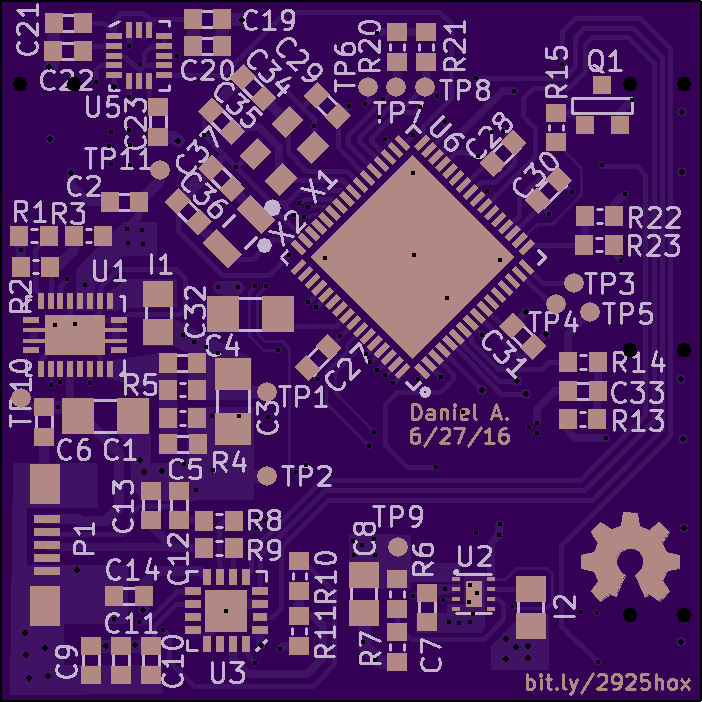

In total I think I spend about 7+ hours designing it. Towards the end I started to get scared I would run out of space to route the traces, but I was able to do it by routing a couple sort traces on the internal power plane. It’s a double-sided load so I’ll use a stencil for the top and hand solder the bottom.
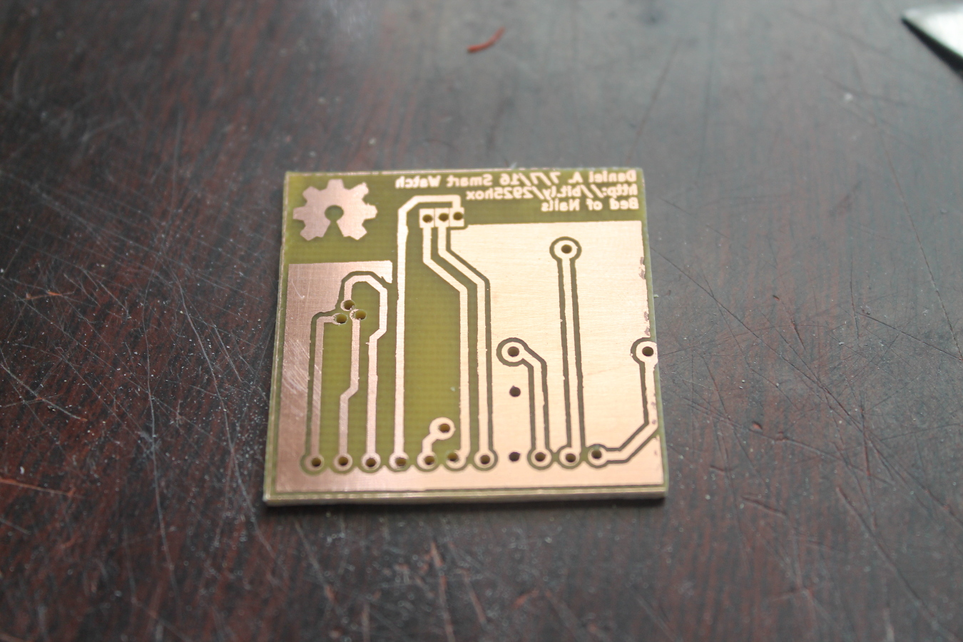
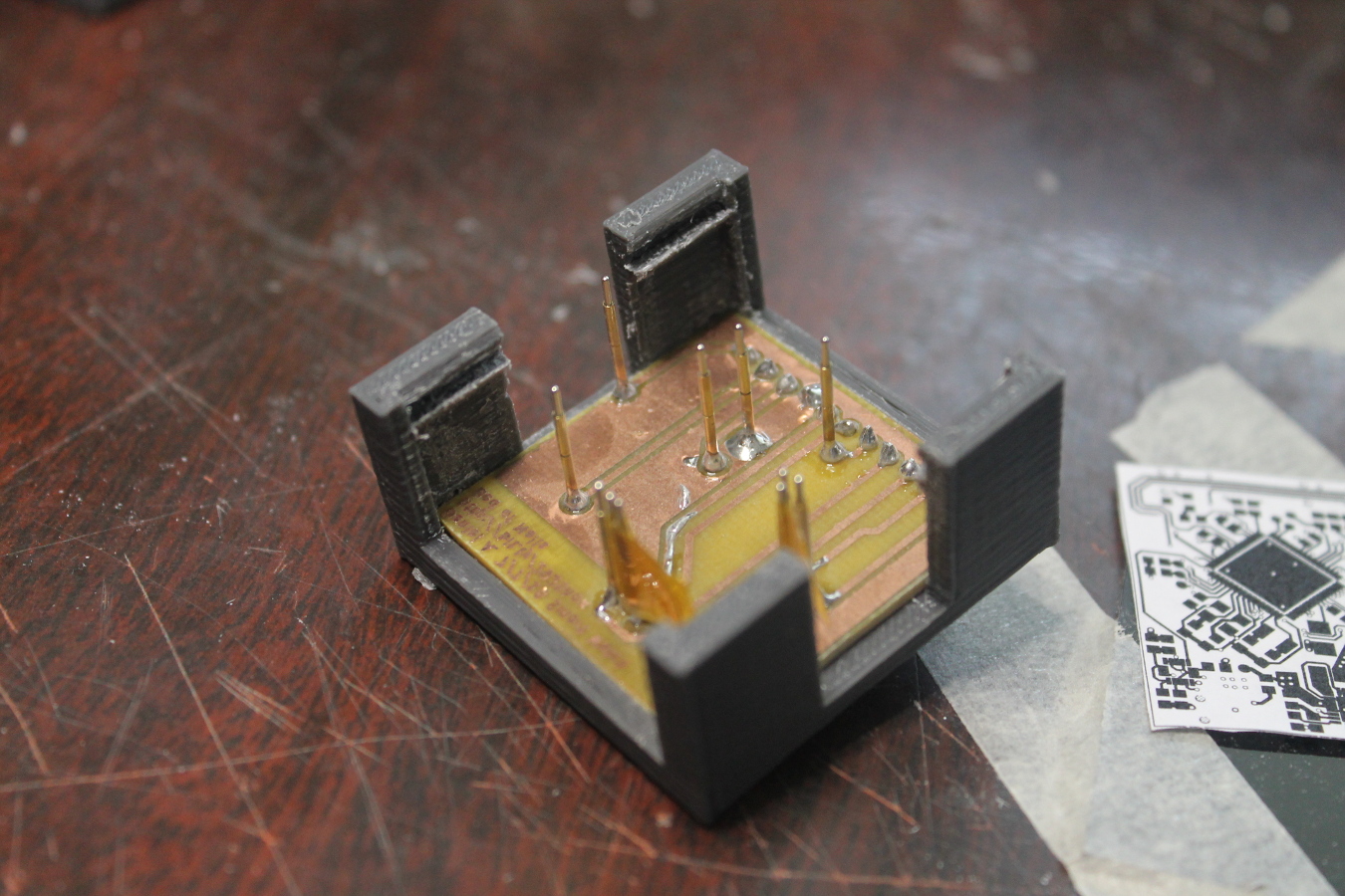
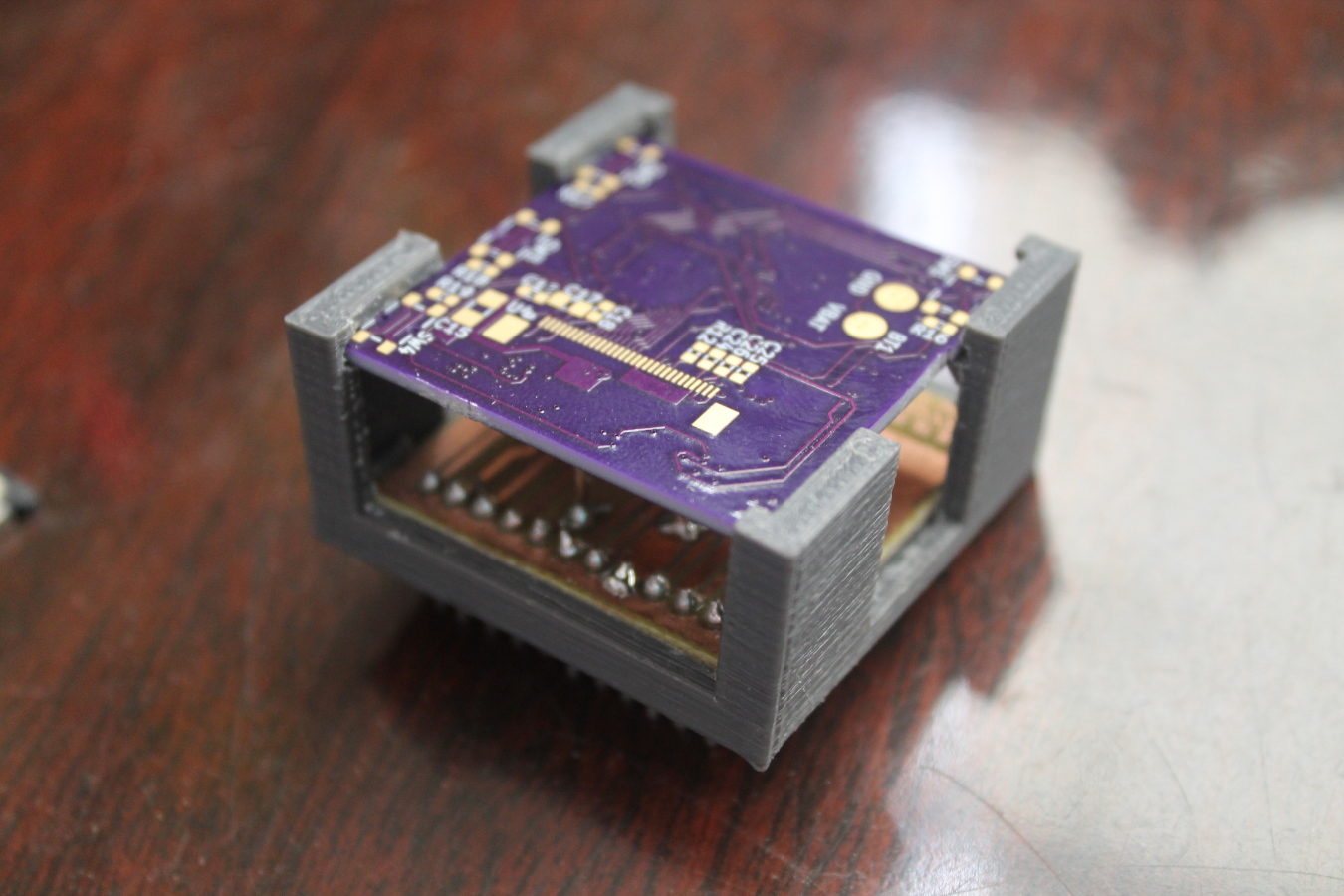
This is the programming jig (bed of nails) for the watch. I etched the PCB myself and the holder is 3D printed. I got the pogo pins off of ebay, 50 for 4 bucks - most likly not the best quality. I had to put some kapton tape between them so they wouldn’t short out.
Update on July 14th 2016
The PCBs came in! I did a dry fit for the jig:

It lined up fine after a little cutting on the jig holder.
So I applied solder paste to the PCB and started placing the components. I got about ten down when I found out that the pads for the battery charger where mirrored! *cries*
I think the reason that happened lies in the datasheet, they didn’t say what orientation the part was in in the pin numbering diagram. Granted, I should have realized that clockwise pin numbering is a little odd to say the least. Well there goes $40+ for the PCB and Stencil, plus the three-weeks it takes to get the board in. Looks like this might not get done before the end of summer after all. :(